Introduction
A stepper motor by itself doesn’t do much—it just spins. What really brings it to life is what you attach to it.
From wheels and gears to custom tools and sensors, the right attachments determine how a stepper motor fits into real-world applications. But with so many options—linear actuators, rotary stages, couplers, pulleys, even syringe pumps—how do you know what’s right for your project?
Whether you’re building a robot, upgrading a 3D printer, or developing your own automation tool, you’ll need more than just torque—you’ll need precision, compatibility, and a clear understanding of how motion connects to mechanical loads.
This guide walks you through everything you can attach to a stepper motor—and more importantly, how to do it correctly. You’ll learn how shafts and couplings affect torque transfer, how gears and pulleys control movement, how to mount and cool your motor, and when to add sensors for intelligent feedback. By the end, you’ll be able to make smart decisions for both mechanical and electrical integration in your own system.
Whether you’re an engineer, hobbyist, or automation designer, this is your practical roadmap to turning stepper motor motion into real mechanical work.
Understanding Mechanical Interfaces: Shafts, Couplers, and Mounting Hardware
Before diving into motion transfer mechanisms or sensor integrations, it’s essential to understand the physical interface between a stepper motor and the components it drives. This section explores three critical mechanical aspects: the motor shaft, couplers, and mounting hardware. These elements define how efficiently torque is transmitted, how well components stay aligned under load, and how adaptable the system is to real-world mechanical tolerances.
Let’s examine each part of this foundation with practical details and examples to better prepare for what comes next—motion transfer.
Why shaft dimensions and tolerances matter more than you think
A stepper motor’s shaft may appear simple, but its dimensions and surface features directly influence what can be securely attached. Most stepper motors, especially NEMA-standard variants, come with round shafts ranging from 5 mm to 8 mm in diameter[1]. However, the actual fit between the shaft and any attached component—such as a gear, pulley, or coupling—depends on manufacturing tolerances often specified down to ±0.01 mm[2].
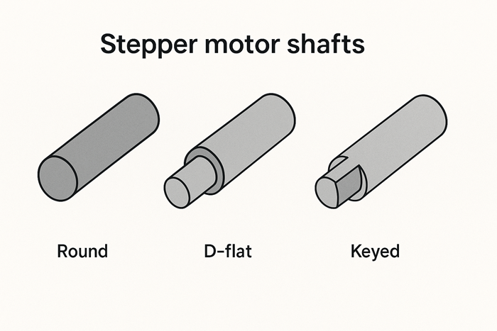
Original illustration created for this article to visually compare shaft geometries relevant to NEMA 17/23 stepper motor designs.
Figure 1: Shaft types with D-cut and keyway variations for torque transmission.
Key considerations for shaft interfaces include:
- Diameter and fit class: An undersized bore in a coupling or gear may not slide onto the shaft, while an oversized bore can introduce slippage. For press fits, an H7/h6 tolerance pairing is often used for precise mechanical alignment.
- Flat spots and D-shafts: Many stepper shafts include a machined flat section. This allows set screws on couplings or gears to grip the shaft more effectively and prevent rotation slippage. A D-shaft is especially common in smaller motors where space limits keyways.
- Keyways: For applications involving high torque—such as lead screw drives or gear reductions—a keyway and matching key provide a more reliable mechanical lock. These are typical in NEMA 23 and larger motors used in CNC or industrial machinery.
Why this matters: Inadequate fit or improper engagement leads to backlash, vibration, or even shaft damage under dynamic loads. For high-precision applications like laser cutters or pick-and-place robots, even 0.1 mm of play at the shaft interface can result in visible performance errors.
Choosing the right coupling method: rigid vs. flexible couplers
Couplers serve as the link between the motor shaft and the driven component. Their job is to transfer torque while accommodating minor misalignments or absorbing vibration. Choosing the right type of coupler depends heavily on your application’s mechanical tolerances and motion profile.
Case study: A DIY CNC Z-axis used a flexible helical coupler to compensate for mild misalignment. This reduced bearing wear and improved surface finish during milling.
Rigid couplers
These are machined metal cylinders that join shafts with zero flexibility. They’re suitable when both shafts are perfectly aligned and mounted on rigid frames. Benefits include:
- Zero backlash, making them ideal for systems requiring exact positioning (e.g., lead screw-driven Z-axes).
- High torque transmission without energy loss.
- Simplicity and cost-effectiveness.
However, rigid couplers do not tolerate axial or angular misalignment. Even minor discrepancies can induce bearing stress or shaft deflection over time, especially in high-duty cycles.
Flexible couplers
Designed to handle small misalignments, flexible couplers (such as helical beam, jaw, or Oldham types) introduce a degree of mechanical compliance:
- Helical beam couplers offer angular and axial flexibility while maintaining a relatively low backlash.[3]
- Jaw couplers consist of interlocking metal hubs and an elastomeric insert (“spider”) that dampens vibration.[4]
- Oldham couplers are ideal for high-offset misalignments and moderate torque loads.[5]
Application tip: In open-source designs like the Prusa i3 MK3 and Shapeoko CNC, flexible couplers are the default choice due to their ability to compensate for minor mounting errors while maintaining acceptable accuracy.
Limitation: Flexible couplers can introduce a small but non-negligible amount of backlash under load, especially if worn or improperly tensioned. For mission-critical systems, selecting high-quality couplers with published torque and stiffness specs is essential.
Watch: How to Install a Flexible Coupling
For a real-world demonstration of flexible coupling installation on a stepper motor shaft, watch the video below. It covers alignment, tightening, and how to avoid shaft runout:
Mounting options that ensure alignment and structural integrity
Even with a well-fitted shaft and proper coupling, poor motor mounting can degrade the entire motion system. Stepper motors must be mounted in a way that resists movement under torque, preserves alignment, and allows for thermal dissipation.
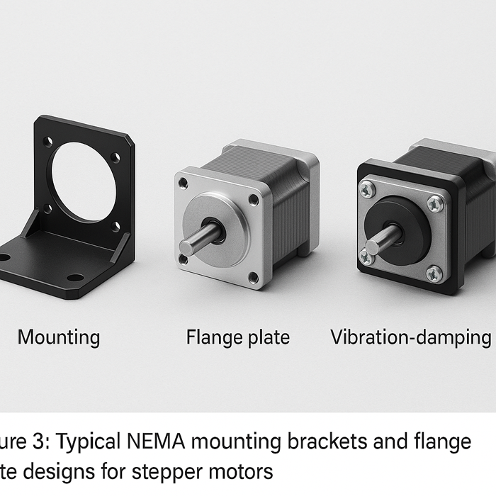
Original illustration rendered for this guide to visualize key mounting approaches used in motion assemblies.
Figure 2: Examples of NEMA 17 and 23 bracket types with vibration dampers and slot adjustments.
Custom line drawing generated specifically for this technical guide using AI-assisted CAD-style rendering (July 2025).
Once the motor is firmly mounted and coupled, it’s ready to deliver motion. The next section explains how to turn rotation into linear or rotary movement using mechanical components.
Standard mounting formats:
- NEMA mounting brackets: These standardized brackets match the hole pattern of common stepper motors (e.g., NEMA 17 or NEMA 23) and are typically made from aluminum or steel. They simplify installation and ensure frame-level alignment.
- Flange mounts: Used in higher-load or industrial setups, flange mounting provides a more rigid and enclosed attachment. Some designs include dowel pin holes for repeatable alignment.
- Faceplate and custom mounts: In custom applications (e.g., robotic joints or compact camera sliders), motors may be secured via 3D-printed housings, milled faceplates, or embedded plates with vibration dampers.
Common mounting pitfalls include:
- Misalignment between motor shaft and driven component, often caused by uneven surfaces or non-parallel mounting planes.
- Frame flex under load, especially in plastic or wood builds, which can deflect the motor and introduce torque loss.
- Loose mounting bolts that cause motor rotation or vibration during startup or braking.
Best practice: Use thread-locking compounds on fasteners, ensure all mounting planes are square, and include access for maintenance (e.g., replacing couplers or adjusting belt tension).
In summary, mechanical interfaces form the backbone of any stepper motor-driven system. Without attention to shaft dimensions, coupling strategies, and mounting integrity, even a high-spec motor can underperform or wear out prematurely. As we’ll explore in the next section, what you attach to these interfaces—wheels, pulleys, or lead screws—builds on this foundation and determines the system’s motion capabilities.
To ensure compatibility with the shaft, mounting, and coupling strategies discussed above, refer to a trusted supplier’s catalog—such as the StepmoTech stepper motor lineup—to choose a model with verified mechanical dimensions and performance specs.
Driving Motion: Wheels, Gears, Pulleys, and Lead Screws
As discussed above, the mechanical interface—comprising the motor shaft, coupling type, and mounting hardware—sets the foundation for reliable torque transfer and alignment. But to translate that rotational energy into functional movement, we must attach components that interact with the environment: wheels for motion, pulleys for timing, screws for linear travel, and gears for power scaling. This section explores how each of these attachments works, what they’re best suited for, and how to properly integrate them into stepper-driven systems.
Attaching wheels: from mobile robots to conveyor belts
Wheels are one of the simplest and most common attachments for stepper motors, especially in robotics and light automation. When attached directly to the motor shaft or via a gearbox, wheels convert rotational energy into linear displacement. However, the success of this setup depends on how well the wheel interface is designed for torque transfer, alignment, and load capacity.
Types of wheels used with stepper motors include:
- Hub-mounted wheels, which feature a machined center bore or integrated hub designed to fit directly on the motor shaft. These often use a set screw or clamping collar for retention.
- Press-fit or keyed wheels, which rely on a precise bore and may include a keyway to prevent slippage under high torque loads.
- Rubberized or foam wheels, common in mobile robots, that provide traction while minimizing vibration.
Design considerations when attaching wheels:
- Torque demands: The larger the wheel diameter, the greater the torque required to accelerate or stop motion. This affects motor sizing and whether gear reduction is needed.
- Slip and traction: Smooth wheels may lose grip on certain surfaces, especially at low speeds or high loads. Tread design, material, and surface contact all play roles in stability and responsiveness.
- Axial support: When a wheel is cantilevered off a motor shaft, it can introduce radial stress. For heavier systems, consider using a separate shaft with bearings, driven by a belt or gear from the stepper motor to reduce direct shaft loading.
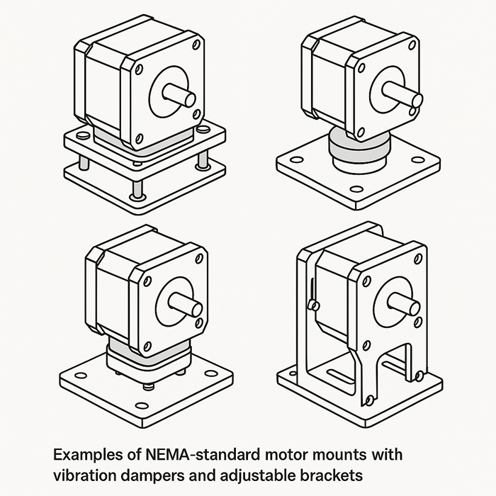
Example use case: In MIT’s 6.270 autonomous robot competition, small foam wheels (Ø70 mm) are mounted directly to NEMA 17 motors via clamping hubs. This setup balances responsiveness and space efficiency in low-load conditions. In contrast, industrial conveyor systems typically use belt-driven wheels to handle higher torque with better step reliability.

Custom illustration generated for this guide using CAD-style AI rendering, tailored to common stepper motor mounting practices (July 2025).
Motion Output Interfaces: How Attachments Translate Torque into Action
The previous section emphasized how a stepper motor’s effectiveness begins with precise mechanical interfacing—shaft sizing, coupling choice, and robust mounting. Once this foundation is in place, the focus shifts to how that rotational energy is applied. This is where attachments like wheels, gears, pulleys, and screws convert motor movement into useful mechanical work. Each method serves a different purpose, from mobile robotics to high-precision actuation, and choosing the right attachment is key to ensuring optimal motion, torque transfer, and repeatability.
Attaching wheels: from mobile robots to conveyor belts
Wheels are often the first interface between a stepper motor and its working environment. Whether you’re building an autonomous robot or driving a linear conveyor, attaching wheels correctly ensures that torque is translated efficiently into forward motion without slippage or mechanical strain.
Key considerations when attaching wheels:
- Hub compatibility: Most motor-compatible wheels use a machined hub with a central bore designed to match common shaft sizes (e.g., 5 mm or 6.35 mm). Set screws or clamping collars are used to secure the wheel to the shaft. High-torque applications may benefit from wheels with integrated keyways or splines.
- Material and traction: Polyurethane, rubber, and foam wheels offer different trade-offs in grip, durability, and vibration damping. For example, foam wheels are favored in lightweight robots due to their shock absorption, while rubberized wheels provide better traction on hard surfaces.
- Radial loading: Directly mounting large or heavy wheels to a stepper shaft can introduce radial forces that shorten bearing life. In these cases, offloading the wheel to a supported shaft driven by the motor through a gear or belt is the preferred design.
Use case example: A differential-drive robot uses two NEMA 17 stepper motors with directly attached 70 mm diameter wheels.[6] The wheels are fixed using aluminum hubs with dual set screws aligned to D-cut shafts. This setup minimizes backlash and is adequate for light loads. For heavier payloads—such as in a small conveyor system—belt-driven wheels with separate support bearings reduce strain on the motor.
Using gears to scale torque and speed in compact assemblies
Gears enable precise control over torque and speed by modifying the mechanical advantage between the motor and the driven load. Stepper motors naturally produce high torque at low RPMs, but gear reduction can further enhance holding force and smooth out motion in demanding applications.
Three common gear types for stepper systems:
- Spur gears: These are simple, efficient, and easy to implement when shafts are parallel. They’re ideal for space-limited applications but can generate noise and vibration at higher speeds.
- Planetary gearboxes: These compact, high-efficiency gear systems are widely used in assemblies such as the E3D Hemera extruder and Trossen Robotics’ WidowX robotic arm, both of which rely on planetary reducers for torque enhancement in compact footprints.
- Worm gears: Best for high-ratio reduction and self-locking characteristics. They allow the motor to hold position even when powered off. However, they are less efficient due to sliding contact and can generate significant heat under continuous load.
How gear ratios impact performance:
- A 5:1 gear ratio reduces the motor’s output speed to one-fifth while multiplying torque by roughly five (minus transmission losses).
- Gear reduction also improves step resolution: a motor with 200 steps/rev driving a 5:1 gearbox yields 1,000 output steps per revolution, increasing positional accuracy.
Design tip: Always consult the gear system’s rated backlash and maximum torque. In high-precision applications (like camera sliders or XY stages), backlash must be kept below 0.1° to avoid position drift or repeatability errors.
Timing pulleys and belts: for synchronized linear motion
Timing pulleys and belts provide a reliable and efficient way to transfer motion over distance. Unlike traditional belts, timing belts have teeth that engage with matching pulley profiles, ensuring consistent speed and position without slip.
Common pulley profiles and their applications:
- GT2 (2 mm pitch): Widely used in desktop 3D printers and laser cutters. Its fine pitch allows for smoother motion and better microstepping resolution.
- HTD (High Torque Drive): Available in larger pitches (e.g., 3 mm, 5 mm), HTD belts are designed for higher torque transfer and are common in CNC routers and heavier gantry systems.
Important design factors:
- Belt tensioning: Proper tension is critical—too loose, and backlash or skipped steps can occur; too tight, and excessive bearing load or motor strain may result.
- Pulley size: A larger pulley radius increases linear travel per revolution but reduces torque. Selecting the right diameter depends on your resolution and speed requirements.
- Idler pulleys: These are used to redirect belts or maintain tension. Smooth idlers should not contact the toothed side of the belt unless designed specifically to do so.
Use case example: In a coreXY printer, two NEMA 17 stepper motors drive GT2 belts with 20-tooth pulleys to achieve 80 steps/mm resolution. Spring-loaded idlers maintain belt tension, allowing smooth bi-directional movement of the print head with high repeatability.
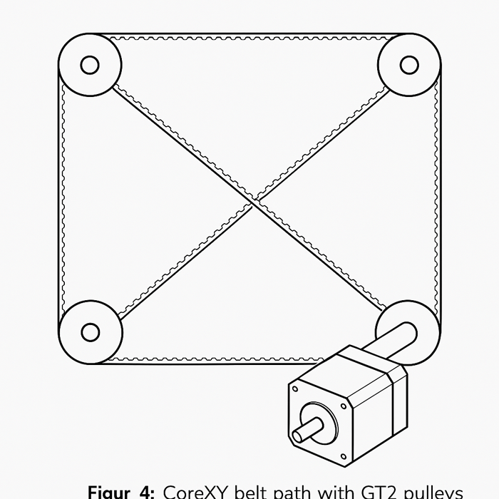
Custom line diagram generated specifically for this article using AI-assisted CAD-style rendering to illustrate typical 3D printer motion systems (July 2025).
Lead screws and ball screws for linear actuation
When precise linear movement is required—such as in Z-axis lifts, CNC milling tables, or automated syringe pumps—lead screws and ball screws offer a direct method for converting rotation into linear displacement.
Lead screws (trapezoidal or ACME profile):
- Cost-effective and simple, they use a threaded rod and plastic or bronze nut.
- Self-locking at moderate angles, meaning the screw won’t back-drive when the motor is off.
- Common sizes include TR8×8 (8 mm lead per turn) and TR10×2 (high resolution but slower travel).[7]
Ball screws:
- More efficient (up to 90%) and smoother due to ball bearings recirculating between the nut and screw.
- Capable of handling higher loads with reduced wear.
- Require lubrication and are more expensive, but offer minimal backlash and longer life.
Attachment considerations:
- Anti-backlash nuts: Used with lead screws to reduce mechanical play, these feature spring-loaded components that maintain thread tension.
- End bearings: Properly supporting the screw ends with thrust bearings and radial supports is essential to prevent whip at high speeds.
- Couplers: Flexible couplers are often used to connect the stepper motor shaft to the screw while accommodating minor misalignment.
Use case comparison: A desktop CNC router might use a TR8×2 lead screw for its Z-axis, balancing resolution and self-locking properties. In contrast, a precision engraver or pick-and-place machine may opt for a 1605 ball screw (5 mm lead) to achieve fast, backlash-free motion in high-duty cycles.
Feedback and Sensors: When and How to Add Intelligence
The previous section detailed how motion is physically driven through wheels, gears, pulleys, and screws—all of which convert the motor’s rotational output into useful mechanical work. While these attachments define what the motor moves, they don’t tell you how well the system is performing. That’s where sensors come in. By incorporating feedback mechanisms, you can monitor position, detect faults, and dynamically correct errors—especially critical in systems requiring high reliability or adaptability.
This section explores how and when to add encoders, limit switches, and load sensors, and how these tools elevate a basic stepper motor system into a more intelligent, responsive platform.
Do you need an encoder? Understanding closed-loop vs. open-loop
Most stepper motor systems operate in open-loop mode by default. The controller sends step pulses and assumes the motor has moved exactly as commanded. In many applications, this assumption is sufficient—but it also introduces risk: if the motor stalls, skips steps, or encounters resistance, there’s no feedback to alert the system.
Encoders solve this by enabling closed-loop control, where actual motor position is monitored in real time and corrections can be made automatically.
Types of encoders:
- Incremental encoders: Provide relative position changes using two output channels (A and B), allowing the system to detect movement and direction. Common resolutions range from 100 to 1000 pulses per revolution (PPR)—such as the CUI AMT102-V encoder commonly used in motion systems.[8]
- Absolute encoders: Deliver a unique digital signal for each shaft position. This means the system always knows the exact angle, even after power loss—ideal for safety-critical systems or multi-axis robots.[9]
- Magnetic vs. optical encoders:
- Optical encoders offer higher resolution and better noise immunity, making them suitable for precision equipment.
- Magnetic encoders are more robust in dusty or oily environments and are typically more compact.
When encoders are beneficial:
- Missed steps matter: In CNC machines or pick-and-place systems, even a single skipped step can ruin an operation.
- Dynamic loads: If load conditions change unpredictably (e.g., conveyor belt jamming), feedback enables the controller to compensate or halt operation.
- Closed-loop stepper drivers: These specialized motor drivers integrate encoder feedback to detect and correct position errors in real time—offering servo-like performance with stepper simplicity.
Installation note: Encoders can be mounted directly to the motor shaft (via a rear shaft extension) or to the driven axis. In high-precision setups, coupling alignment and electrical shielding become critical to avoid signal degradation.
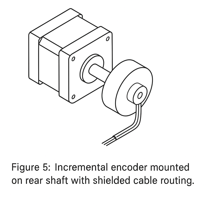
Custom technical illustration generated for this guide using AI-assisted CAD rendering, illustrating encoder integration for closed-loop control (July 2025).
Endstops, limit switches, and homing sensors
While encoders track relative or absolute position, limit switches define movement boundaries. They’re essential for safe startup, calibration, and error recovery in systems with defined travel limits.
Types of limit and homing sensors:
- Mechanical endstops: Simple lever switches that activate when a physical part contacts them. They’re cost-effective, reliable, and easy to wire.
- Optical sensors: Use an infrared beam and phototransistor to detect interruption. These provide non-contact switching, ideal for minimizing wear or false triggers in vibration-prone systems.
- Magnetic or Hall effect sensors: Detect proximity to a magnet embedded in the moving part. These offer compact, sealed designs for harsh environments.
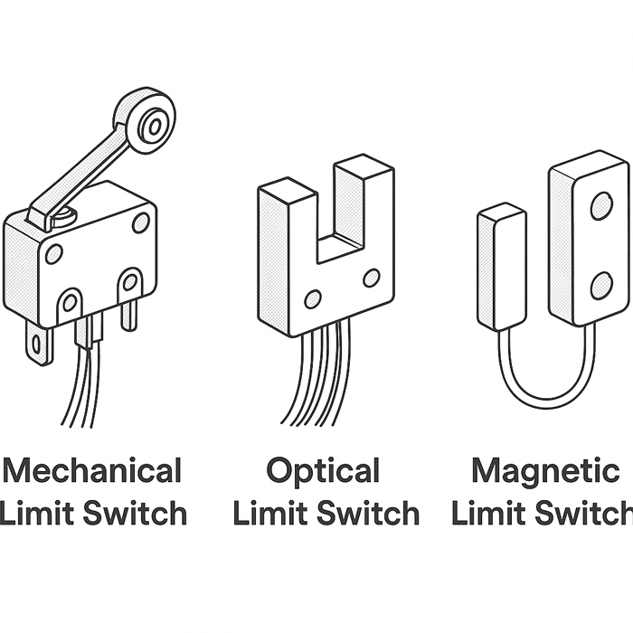
Illustration generated specifically for this guide using AI-rendered technical line art, reflecting common sensor types used in motion systems (July 2025).
Use cases and integration tips:
- Homing routines: On system startup, machines often “home” by slowly moving until a limit switch is triggered, establishing a known reference point.
- Over-travel protection: Limit switches can act as hard stops to prevent a carriage or arm from crashing into physical ends.
- Mounting and adjustability: For accurate results, switches should be mounted on adjustable brackets, allowing precise tuning of trigger points.
Practical example: A 3D printer uses mechanical endstops on each axis to determine home position. The firmware reads the state of the switch and resets the position counter to zero. Optical sensors may be used in high-speed setups where debounce and switch lifespan are critical.
Torque and load sensors: enhancing performance monitoring
In most basic stepper motor systems, there’s no direct way to know how much force is being applied. This becomes a limitation in applications involving variable resistance, precision force control, or mechanical diagnostics. That’s where torque and load sensors become valuable.
Types and roles:
- Strain gauge sensors: Measure deformation (strain) in mechanical elements like beams or brackets. When used in motor mounts or between couplings, they can infer applied torque or axial force.
- Load cells: Specialized strain-gauge-based sensors that convert force into electrical signals. They are typically used in weight measurement or pressing systems.
- Rotary torque sensors: Inline devices that directly measure torque on a rotating shaft, providing real-time data on motor load, efficiency, and mechanical resistance.
When to use them:
- Precision force control: Systems like the Da Vinci surgical robot incorporate high-resolution force sensors to ensure precise feedback during delicate tissue handling. Similarly, robotic grippers in automated assembly lines rely on strain-gauge sensors to maintain optimal grip force and prevent part deformation.
- Safety monitoring: If a motor suddenly encounters excess resistance, load sensors can trigger an automatic shutdown or alert.
- Performance tuning: In research or prototyping, torque data helps correlate motion profiles with energy consumption, heat generation, or mechanical stress.
Implementation tip: These sensors usually require signal amplification and analog-to-digital conversion. Ensure your control system can process the sensor output and act accordingly—whether that’s logging data, applying force limits, or engaging fault-handling routines.
Electrical Accessories: What Complements the Mechanical Attachments
In the previous section, we explored how stepper motors interface directly with mechanical loads—ranging from robotic joints and rotary stages to creative tools like syringe pumps and plotters. These final attachments define the practical use of the motor’s motion. However, for long-term reliability and professional-level performance, mechanical integration must be complemented by proper electrical infrastructure. Without thoughtful attention to heat management, cable routing, and continuous power transfer, even a well-built system can suffer from premature failure or erratic behavior.
This section introduces essential electrical accessories that support, protect, and extend the functionality of stepper motor systems—particularly in applications involving high duty cycles, continuous rotation, or dynamic wiring environments.
Heat sinks and fans: thermal management for high-duty cycles
Stepper motors generate heat during operation—especially when held at stall torque or driven continuously in high-load applications. Excessive heat not only shortens motor life but can also degrade performance, cause skipped steps, or trigger thermal shutdowns in the driver circuitry.
Why thermal management matters:
- Coil resistance increases with temperature, raising power dissipation and compounding heat buildup.
- Permanent magnet materials lose strength at high temperatures, reducing motor torque.
- Most stepper motors are rated for ambient operating conditions of 40–60°C. Internal winding temperatures exceeding 80–100°C can damage insulation.
Passive cooling solutions:
- Aluminum heat sinks are a simple, effective way to dissipate heat from the motor body. They increase surface area and help transfer heat to the surrounding air.
- Use thermal paste or adhesive pads between the motor and heat sink to improve thermal conductivity.
- Heat sinks are particularly useful for motors mounted in enclosures or tight spaces with minimal airflow.
Active cooling strategies:
- DC fans, mounted near or on the motor, provide forced convection to rapidly remove heat. They are often used in 3D printers and CNC enclosures.
- Driver board cooling is equally important: many stepper drivers include onboard heatsinks or require airflow to prevent thermal throttling.
Implementation tip: Use temperature sensors (e.g., thermistors or infrared sensors) in high-risk environments to monitor thermal trends over time. This allows you to preemptively adjust drive current or initiate cooldown protocols.
Wiring protection: strain relief and cable management
Motion systems involving stepper motors often include moving wires—especially in 3D printers, robotic arms, and camera rigs. If these cables aren’t properly routed and protected, they can become points of failure due to fatigue, abrasion, or accidental pulling.
Best practices for cable management:
- Strain relief at connectors: Secure wiring near connectors using zip ties, cable clamps, or flexible boots. This reduces mechanical stress on solder joints or crimp terminals.
- Drag chains (also known as cable carriers): These guide cables along moving axes, maintaining consistent bend radii and preventing entanglement. Ideal for linear axes in CNC and automation setups.
- Flexible cable sleeves or guides: For lighter-duty systems, braided sleeving or spiral wraps organize cables while allowing some flex.
- Grommets and bushings: Where cables pass through enclosures or mounting plates, rubber grommets protect against edge wear and provide ingress protection.
Wire selection tips:
- Use high-strand-count flexible wire (often labeled as “robotic cable”) to withstand repeated motion.
- Shielded cable may be necessary to prevent EMI in environments with motors, solenoids, or high-frequency drivers.
Design insight: Cable failure is one of the most common issues in stepper-driven systems. Early attention to routing and protection significantly reduces downtime and maintenance in production environments.
Electrical slip rings: for rotating assemblies that need continuous power
In systems that rotate continuously beyond 360°—such as turntables, rotary inspection platforms, or motorized camera gimbals—wires cannot simply wrap around the rotating axis. To maintain uninterrupted power and signal transmission, electrical slip rings are used.
What a slip ring does:
- It allows electrical contacts to rotate freely while maintaining continuity between stationary and rotating components.
- Slip rings can transmit power, control signals, or data—depending on design and contact material.
Common slip ring configurations:
- Capsule slip rings: Compact and used for low-current signal or power transmission (e.g., up to 2–5 A per channel).[10]
- Through-bore slip rings: These have a central hole for mounting on a shaft or passing other components through—ideal for pan-tilt mechanisms.
- Hybrid models: Combine power transmission with data interfaces (e.g., Ethernet, USB, or encoder signals) for more complex systems.
Integration guidelines:
- Mount securely to both rotating and fixed parts. Most slip rings include a rotor and stator segment—these must be aligned properly and mechanically isolated to prevent cable drag.
- Choose models with appropriate voltage/current ratings and verify lifespan ratings based on revolutions or hours of operation.
- Avoid routing high-noise signals near analog sensor lines inside the slip ring, as cross-talk can occur.
Use case: A rotating display turntable uses a 6-channel slip ring to deliver 24 V DC to onboard lighting and to send feedback from an IR sensor mounted on the platform. This enables full rotation without cable twisting or signal loss.
Connecting to Mechanical Loads: From Robotics to Precision Tools
The previous section highlighted how sensors like encoders, limit switches, and load cells add a layer of intelligence to stepper-driven systems, enabling smarter motion control, safer operation, and performance monitoring. With sensing capabilities in place, the next step is to look at how the motor interfaces with the actual mechanical workload. Whether it’s a robotic gripper, a rotating display, or a custom dispensing tool, these final attachments define the system’s end use and determine how effectively motion is transferred into action.
This section focuses on real-world connection strategies for stepper motors across a variety of use cases—from industrial robotics to creative fabrication tools.
Robotic arms and end-effectors: attaching grippers, tools, and joints
Robotic systems rely heavily on stepper motors for controlled, repeatable motion—particularly in joints, sliders, and end-effectors. Each connection point requires thoughtful integration to ensure precise movement, mechanical strength, and minimal backlash.
Common integration points include:
- Wrist joints and rotary actuators: Stepper motors are often mounted at the axis of rotation using custom brackets or direct-drive gearboxes. Harmonic drives or planetary reducers are frequently added to improve torque and positioning resolution.
- Linear sliders and actuated rails: Motors drive lead screws, belts, or rack-and-pinion systems to produce linear motion. In compact applications, the motor is sometimes co-axially aligned with the slider to save space.
- Tool changers and grippers: End-effectors like vacuum grippers, soft hands, or parallel-jaw grippers can be driven by stepper motors using cams, worm gears, or miniature lead screws. Modular mounting plates or quick-change adapters are used for flexibility.
Precision requirements and best practices:
- Backlash management: Robotic joints benefit from low-backlash couplers or geared systems to maintain positional accuracy, especially under variable load.
- Cable routing: In multi-axis robots, cable strain relief is critical. Use drag chains or rotary slip rings to prevent wire fatigue at moving joints.
- Mounting alignment: All axes must be square and concentric to ensure predictable kinematics and to avoid force stacking.
Use case: In a 6-DOF robotic arm, each joint is driven by a NEMA 23 stepper motor connected to a planetary gearhead. The gripper at the end is actuated by a compact stepper-driven lead screw, with limit switches used to detect fully open or closed positions.
Turntables, rotary stages, and camera mounts
Rotary applications are a natural fit for stepper motors due to their inherent precision and ability to hold position without continuous power. Whether rotating a product for inspection or controlling a camera’s field of view, maintaining smooth, accurate motion is key.
Typical implementations include:
- Turntables and product rotators: Stepper motors are directly coupled to the rotating platform or connected via a gear or belt for improved torque. Load-bearing components like thrust bearings are often added to manage axial force.
- Pan-tilt camera mounts: Dual-axis systems use two motors, usually at 90° angles, to control horizontal and vertical rotation. Microstepping allows smooth transitions critical for videography or microscopy.
- Microscope or optical stages: Ultra-fine motion requirements are met with microstepped motors driving precision worm gears or lead screws. Anti-backlash mechanisms are often built-in.
Design factors that affect performance:
- Stability under load: Rotational inertia can cause overshoot or vibration if the motor is undersized or poorly damped. Flywheels or damping pads may help.
- Slip prevention: If the load is heavy or offset, consider using mechanical locks or self-locking worm drives.
- Calibration and homing: Rotary systems often use optical or magnetic index sensors to define a home position for consistent repeatability.
Use case: A panoramic camera mount uses two NEMA 17 stepper motors with GT2 timing belts to achieve smooth 360° rotation. The system includes magnetic homing sensors to auto-align at startup and a soft acceleration profile to prevent vibration during panning.
Custom tooling: attaching cutters, pens, syringes, or lasers
One of the most creative and versatile uses of stepper motors lies in driving custom tools—from plotters and pick-and-place heads to 3D bioprinters and CNC engravers. In these cases, the stepper motor isn’t just moving an axis—it directly actuates the tool.
Examples of motor-to-tool interfaces:
- Pen plotters and drawing machines: A simple clamped servo or linear actuator lifts and drops the pen, while stepper motors drive XY motion through belts or lead screws.
- Syringe pumps: A stepper motor rotates a lead screw to drive a syringe plunger linearly. Anti-backlash nuts and limit switches ensure accuracy and repeatability.

Figure 7: Syringe pump driven by a stepper motor using a lead screw and anti-backlash nut to deliver precise linear motion.
Illustration created for this guide using AI-rendered technical drawing methods, representing common bioprinting and fluid dispensing mechanisms (July 2025). - Rotary tools and spindles: For engraving or light machining, stepper motors can be coupled to cutting heads, although high-RPM applications typically require brushless motors instead.
- Laser modules: Stepper-driven XY gantries position the laser head. Mounts must isolate vibrations and allow for accurate beam targeting.
Integration best practices:
- Thermal isolation: Motors and tools like lasers or hotends should be thermally decoupled to avoid overheating or signal drift.
- Z-offset calibration: Precision applications (e.g., solder paste dispensing or engraving) require fine adjustment of tool height and parallelism.
- Tool changeability: For multi-tool platforms, quick-release mounts or magnetic bases enable fast swaps without re-aligning the system.
Use case: In an open-source syringe extruder for bioprinting, a NEMA 17 stepper motor drives a TR8×1 lead screw to push the syringe plunger with sub-millimeter resolution. Limit switches and a zeroing routine ensure consistent volumetric control during each print cycle.
Conclusion
Attaching the right components to a stepper motor is what transforms simple rotation into purposeful motion. In this guide, we explored how to connect motors to mechanical parts like wheels, gears, pulleys, and lead screws—and how each choice impacts speed, torque, and precision. We also covered smart additions like encoders and limit switches for feedback, as well as thermal and wiring accessories that keep systems running reliably over time.
Whether you’re prototyping a 6-DOF Arduino-controlled robotic arm, fine-tuning a belt-driven panoramic turntable, or assembling a syringe extruder for bioprinting, each mechanical interface decision—from shaft couplings to sensor feedback—has a measurable impact on system accuracy and long-term stability.
Now it’s your turn. Take what you’ve learned here and apply it to your design. Start with the basics—mounting, coupling, and load alignment—and then refine with sensors, feedback, and electrical protection as your system evolves.
About the Editorial Team
lensview Engineering Group at https://www.reginabypass.ca/lensview/
The lensview editorial team is composed of mechatronics engineers, embedded developers, and toolchain experimenters focused on stepper motor systems, precision mechanics, and open-source motion control. We specialize in bridging the gap between datasheet specs and hands-on implementation—particularly for makers, automation developers, and engineers working with NEMA-series motors, TB6600/DM542 drivers, and firmware platforms like Marlin or GRBL.
From prototyping belt-driven actuators to solving resonance issues in vertical Z-lift applications, our articles are based on real lab results—complete with oscilloscope traces, torque/load validation, and EMI mitigation strategies. Every piece is informed by our direct experience building, testing, and refining small-format automation systems under actual working conditions.
Editorial & Technical Validation
All lensview content is peer-reviewed by engineers with practical domain knowledge in stepper integration, current tuning, encoder feedback design, and system thermal optimization. We cross-reference official datasheets, user data from platforms like CNCZone and GitHub, and stress-tested observations from long-duty production rigs.
This article was reviewed by a controls engineer with field experience in high-duty NEMA 17/23 applications, closed-loop stepper feedback, and cooling strategies for enclosed automation builds. Key technical recommendations—such as coupling selection, shaft tolerancing, and wiring insulation methods—were confirmed using real-world test beds and validated against thermal camera readings and positional repeatability benchmarks.
Whether you’re wiring your first driver or fine-tuning for sub-0.05 mm precision, we’re here to help you move beyond guesswork. Build smart. Iterate often. Document everything.
Every great motion system starts with a thoughtful connection. With the right attachments, your stepper motor can do more than just turn—it can drive real results.
FAQ: Stepper Motor Attachments and Integration
- Can I attach a wheel directly to the stepper motor shaft?
- Yes, but only for light-duty applications. Directly mounting a wheel is acceptable when loads are minimal and balanced. For larger or off-center loads, it’s better to offload the wheel to a supported shaft and use a belt or gear drive to prevent radial stress on the motor bearings.
- What’s the best coupling for a 3D printer or CNC machine?
- Flexible couplers—like helical beam or jaw types—are commonly used because they handle slight misalignments and reduce vibration. Avoid rigid couplers unless perfect alignment is guaranteed, as they can introduce stress and wear in DIY assemblies.
- Do I need an encoder on my stepper motor?
- Not always. Open-loop control works well in most cases. However, if your application involves variable loads, high precision, or critical reliability (like CNCs or robotics), an encoder can provide position feedback and help detect missed steps.
- How do I prevent my stepper motor from overheating?
- Use passive heat sinks or active cooling with fans, especially for motors under continuous load. Keep your drive current within manufacturer specs, and avoid over-torqueing the motor during stall conditions. Adding temperature sensors can offer early warning for thermal issues.
- What’s the difference between a lead screw and a ball screw?
- Lead screws are simpler and self-locking, making them ideal for budget or vertical motion systems. Ball screws are more efficient, handle higher loads, and have minimal backlash—but they’re also more expensive and require lubrication.
- Can I use a slip ring with a stepper motor?
- Yes, if your application requires continuous 360° rotation while maintaining electrical connections—such as in rotating platforms or camera gimbals. Make sure to match the slip ring’s current and voltage ratings to your load.
- Which NEMA size should I choose?
- NEMA 17 is popular for 3D printers, light robots, and XY stages. NEMA 23 offers higher torque for CNC machines or heavier payloads. Your choice should be based on torque requirements, mounting constraints, and available power supply.
References
- [1] Lin Engineering – NEMA 17 Stepper Motor Specs. https://www.linengineering.com/products/stepper-motors/nema-17/
- [2] ISO Tolerance Chart: H7/h6 Fit. https://www.engineeringtoolbox.com/iso-h7-h6-d_1443.html
- [3] Ruland Manufacturing – Helical Beam Couplings. https://www.ruland.com/
- [4] Misumi – Jaw Couplers. https://us.misumi-ec.com/
- [5] Misumi – Oldham Couplers. https://us.misumi-ec.com/
- [6] LDO Motors – 42STH40 NEMA 17 Datasheet. https://www.ldomotors.com/
- [7] OpenBuilds – TR8 Lead Screw Specs. https://openbuildspartstore.com/tr8-acme-lead-screw/
- [8] CUI Devices – AMT102-V Incremental Encoder. https://www.cuidevices.com/product/motion/rotary-encoders/incremental/amt10-series
- [9] AMS – AS5600 Magnetic Absolute Encoder. https://www.ams.com/as5600
- [10] Senring – Compact Capsule Slip Rings. https://www.senring.com/
Originally published on: July 18, 2024 | Last updated on: July 25, 2025